g8gyw.github.io
QRP DIGITAL RF POWER & VSWR METER
INTRODUCTION
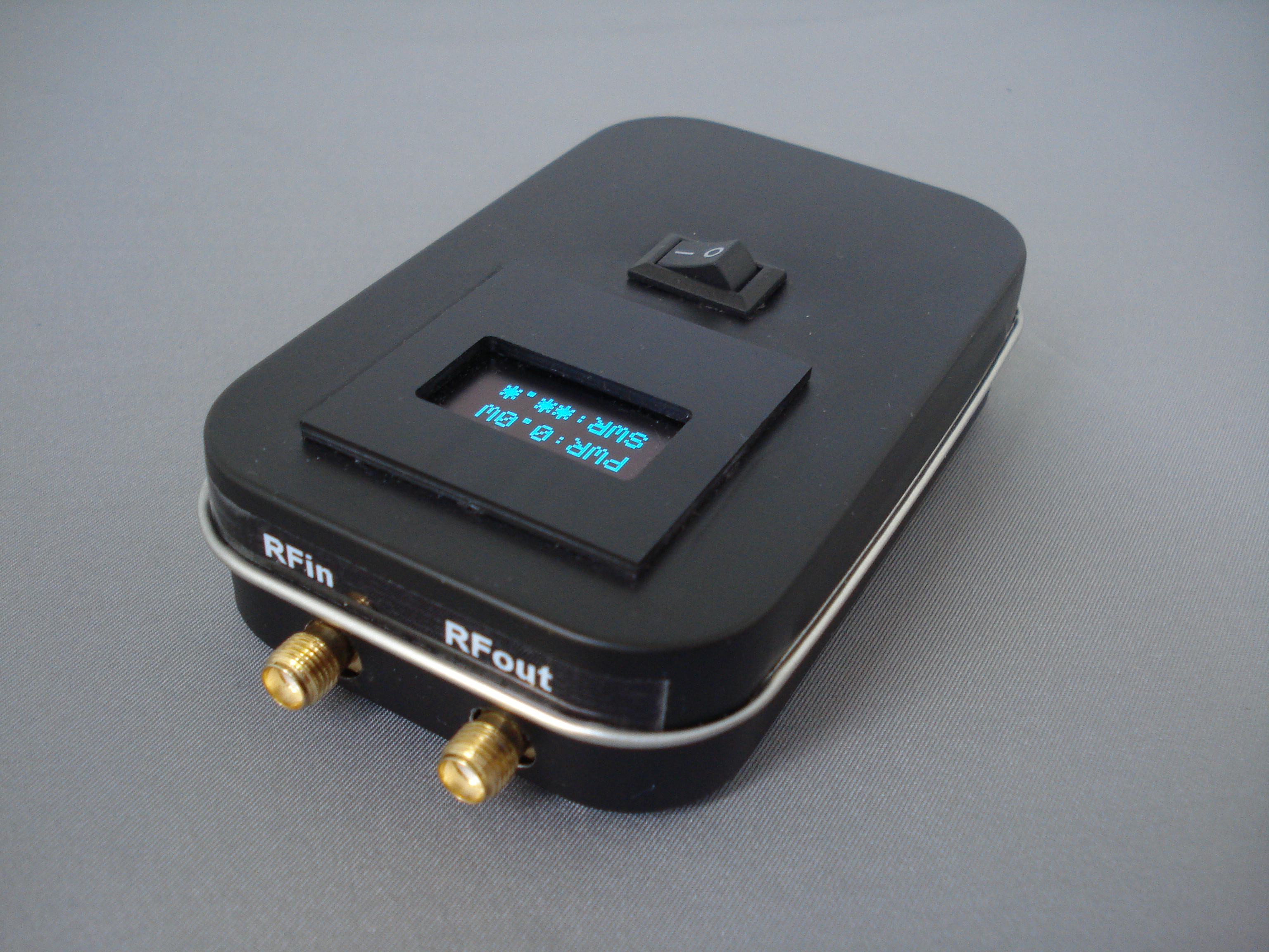
Here is a design for a digital QRP RF power meter that fits in a tobacco tin, complete with battery and charger. It displays average power from 0.5 Watts to 12 Watts, VSWR and battery voltage. The component cost, excluding PCB and display bezel, was around £25.
SCHEMATIC
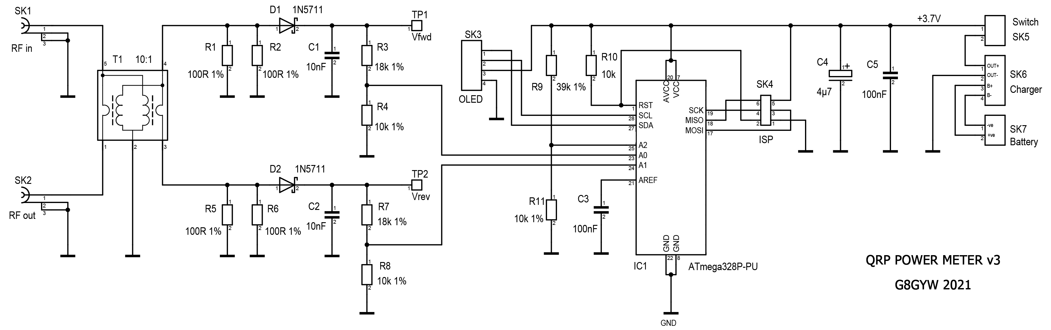
DESCRIPTION
The design utilises a Tandem coupler (also known as a Stockton bridge). I used a binocular core instead of the usual pair of toroids as this was smaller and easier to construct. A 10:1 turns ratio provides 20dB of coupling and 20 to 40dB of directivity up to 50MHz.
The input waveform is half wave rectified by a 1N5711 Schottky diode. The resulting dc voltage on TP1 is:
Vfwd = (Vinpk-pk / 20) - Vdiode
where Vdiode is the 1N5711 forward voltage drop (typically 0.33V).
The DC voltages representing forward and reverse power are fed to two ADC inputs on an Atmega328p processor. To save components this runs on its internal 8MHz clock and the internal 1.1V bandgap reference is used as the ADC reference. A third ADC input is used to monitor the voltage of the rechargeable battery. The display is a 3.3V compatible 0.96" 128x64 OLED.
My first attempts to calculate forward and reverse power were based on this equation:
Pfwd = (20 * (Vfwd + Vdiode))2 / 400
While this worked well for forward power there was a problem when calculating VSWR because even with a perfect match, where the reverse power is zero, the equation gives a minimum value of about 100mW due to the presence of the Vdiode term.
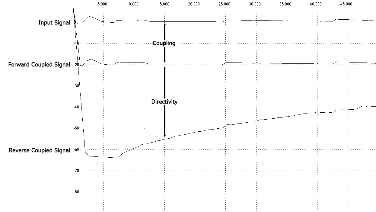
I plotted the response of three prototype boards using the excellent Veusz program (https://veusz.github.io/) and performed a quadratic curve fit of the form ax2 + bx. This returned the values a = 1.0 and b = 0.75 and gave a close fit without the troublesome offset at low power levels.
These curves can be seen in the graph below.
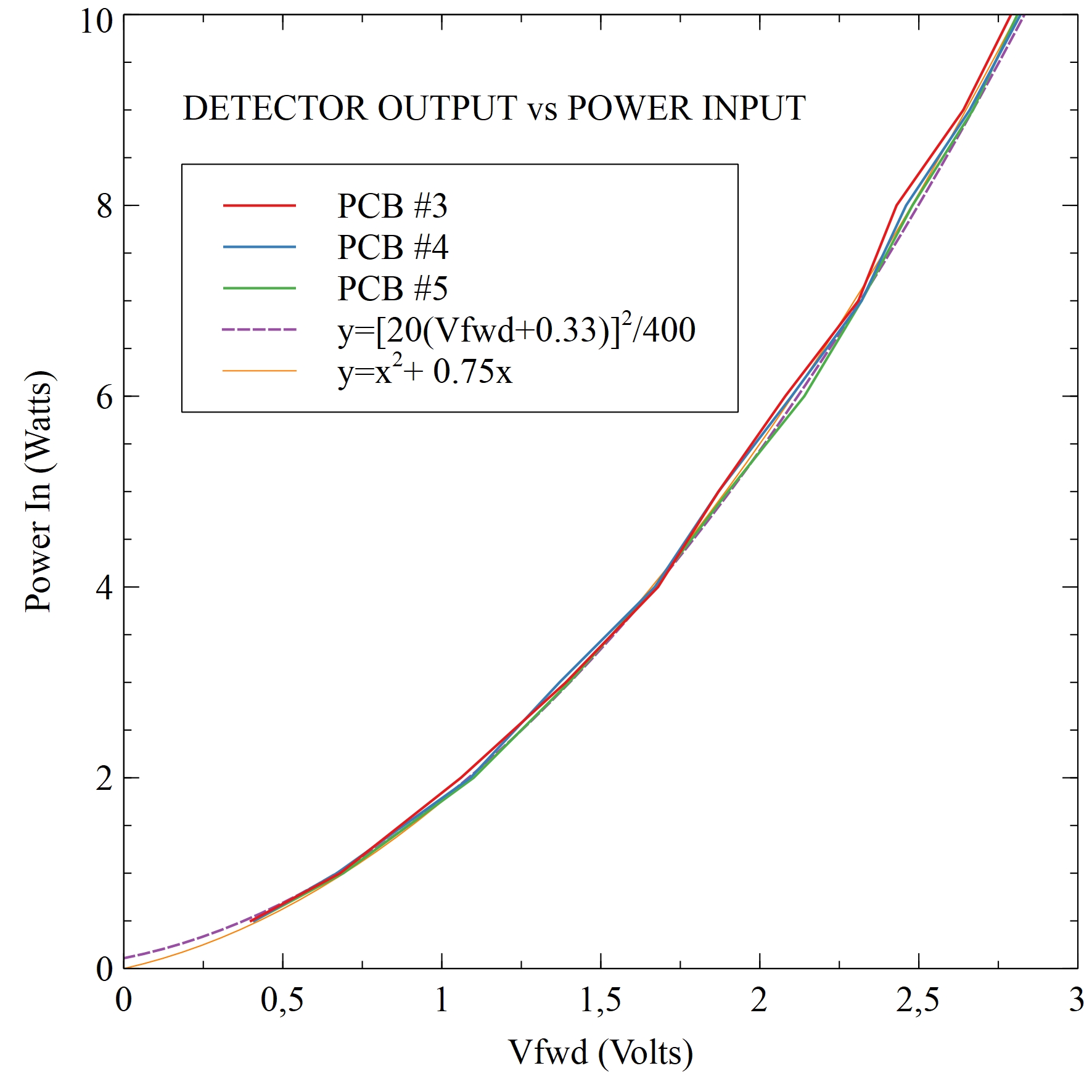
If necessary, the values of a and b can be adjusted in the software to suit the characteristics of the diodes used.
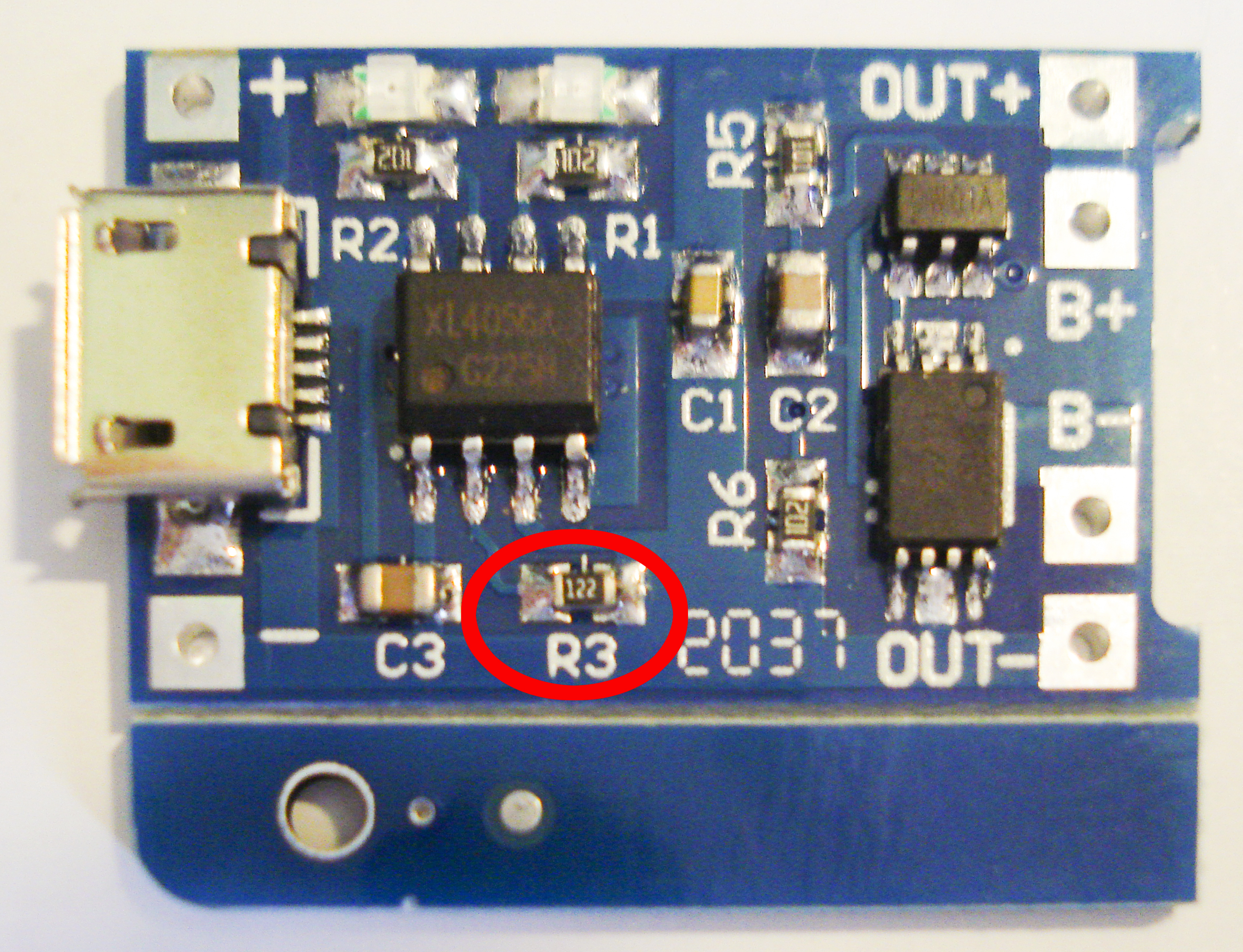
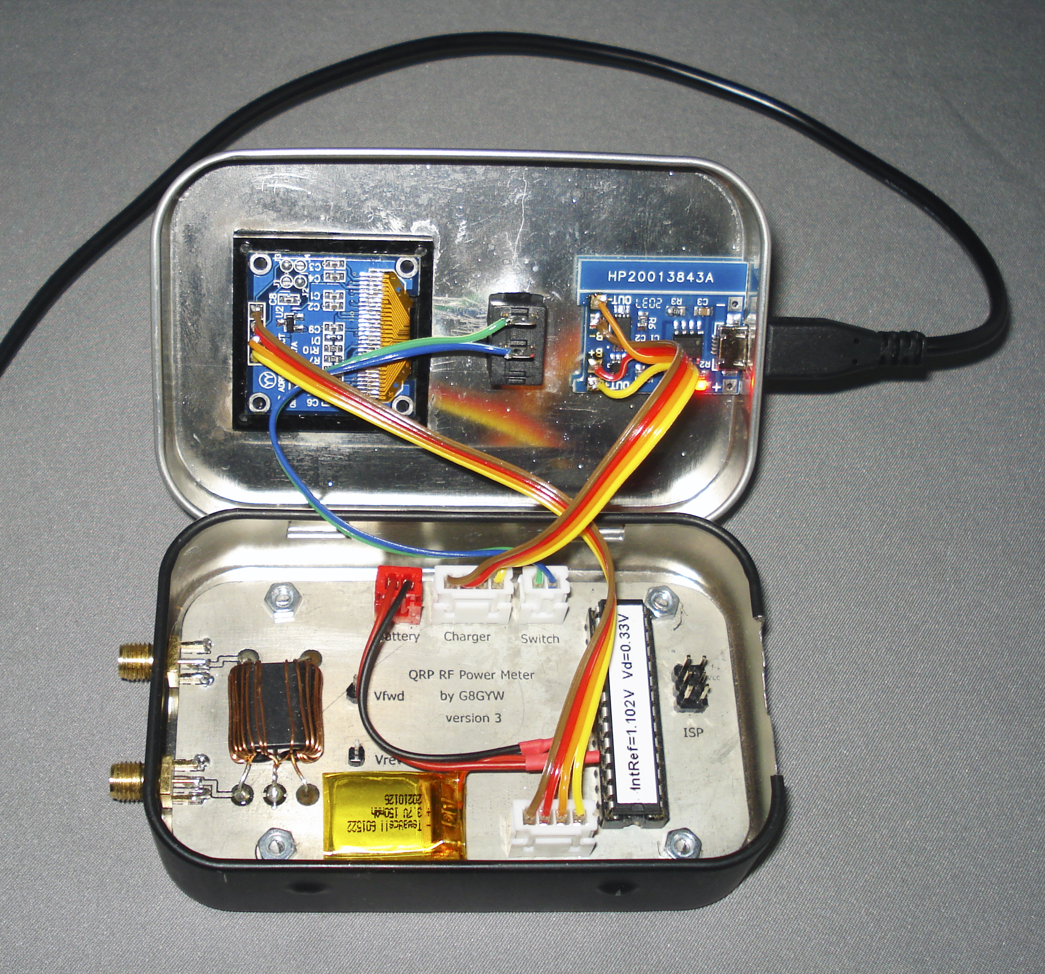
The battery is a 3.7V 150mAh Lithium-Ion Polymer cell as used in many radio controlled models. These are fitted with a PCB that provides protection against overcharging and short circuits, but it is important that they are charged correctly (constant current at 1C then constant voltage at 4.2V). Fortunately a small charging module based on the TP4056 IC is available very cheaply and all you need then is a USB lead and 5 Volt supply. You will also need to change a surface mount resistor on the charger board to set the current to the correct value (150mA). This is shown in the photograph below, and the value I used was 8.2k. When using the charger you have to open the tin lid to see the status LEDs, but you could remove these and wire the pads to panel mounted ones instead.
The software is provided as an Arduino sketch. The code includes typical values for the processor's bandgap reference and the calibration factors. These parameters can be adjusted during initial testing.
CONSTRUCTING THE TRANSFORMER
Winding the transformer is straightforward. Pass 10 turns of 27swg enamelled copper wire through each hole in the core then strip, twist and solder the two wires at one end. With the twisted pair at the bottom, pass a single turn of 24swg wire through the left hand hole, bend the right hand wire on the other side across to meet it and solder together. Finally, pass a single turn of 24swg wire through the right hand hole, bend the left hand wire across and solder. The four stages are shown below.
![]()
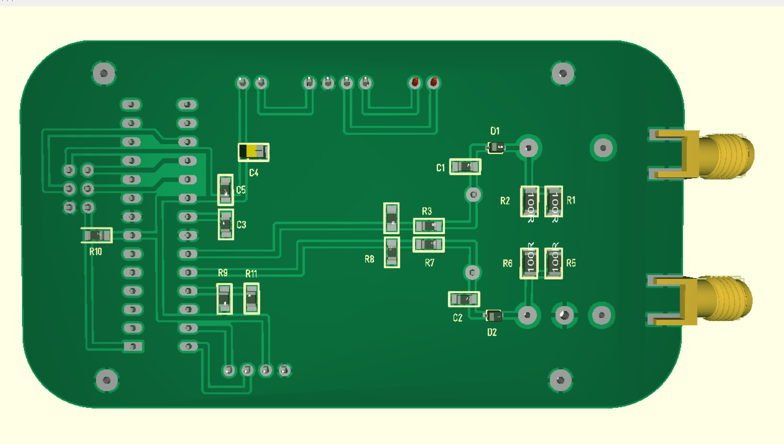
BUILDING THE PCB
The PCB layout files are here:
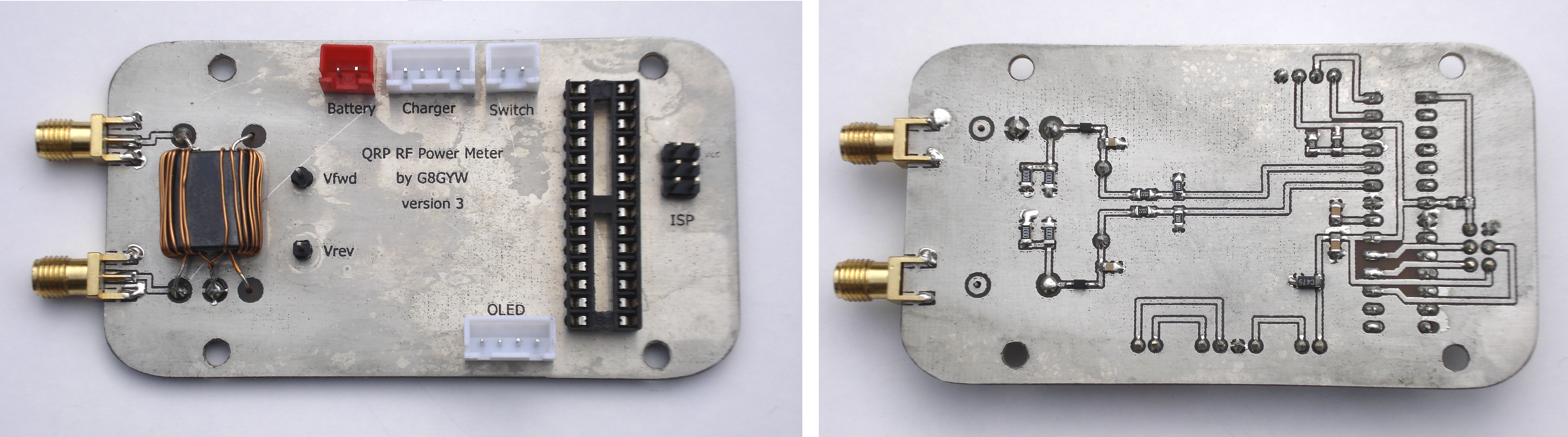
Everyone has their own favourite method for making PCBs. I use a laser printer, toner transfer paper, a laminating machine and ferric chloride. When both sides are etched and the board is drilled I use an electroless tin plate solution to protect it from tarnishing.
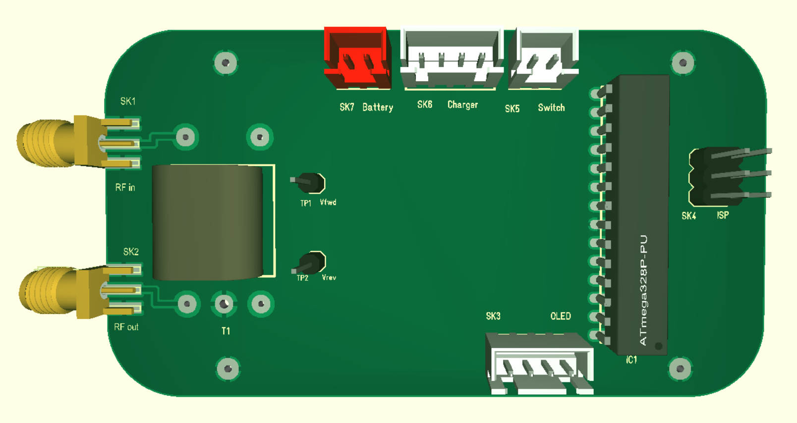
Start the assembly by soldering the surface mount components on the bottom side. You will need a soldering iron with a fine tip, some 0.5mm diameter solder wire, flux and strong reading glasses. The Schottky diodes are particularly small and it's difficult to see the polarity marking. Finish off by fitting the connectors and transformer on the top side. I used a socket for the processor but, as it's difficult to remove the IC once the PCB is fitted in the tin, I included an In-System Programming connector (ISP). Note that the SMA connectors and the earth wire of the transformer are soldered on both sides of the board to bond the ground planes. Further bonding is provided by the four fixing screws.
When assembly is complete it's a good idea to do some basic checks before fitting the processor and mounting the board in the tin.
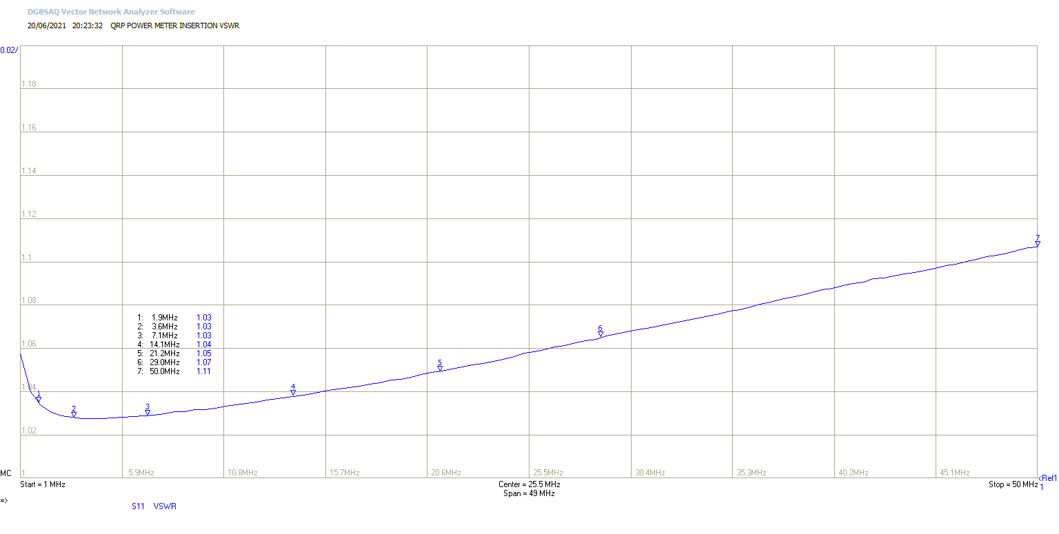
First inspect the PCB carefully for short circuits. If you have a VNA you can check the impedance of each RF connector with the other terminated; they should both be 50 ohms. Then, with RF out terminated, apply an HF signal between 1 and 10 Watts to RF in. If you don't have another RF power meter to hand you can check the level with an oscilloscope and x10 probe connected to the transformer by using the formula Power = Vpk-pk2 / 400. Measure the DC voltage on TP1 and compare the result with the Table below.
| Power In (Watts) | Volts In (pk-pk) | TP1 (Vfwd) |
|---|---|---|
| 1 | 20.0 | 0.7 |
| 2 | 28.3 | 1.1 |
| 5 | 44.7 | 1.9 |
| 10 | 63.2 | 2.8 |
If everything looks good then the board can be fitted to the case. Tobacco tins are much easier to work with than aluminium cases. I cut out the rectangular hole for the display bezel with a small cutting disk in a Dremel. The other holes were made with drills and files. The PCB is attached to the tin with four M3 screws with nuts underneath to act as stand-offs. The display bezel is glued to the tin and the battery and charger are attached with sticky pads.
PROGRAMMING
There are several ways of programming the processor. My preferred method is to use the Arduino IDE with the MiniCore Board Manager and a USBasp programming adapter.
Insert the Atmega328P into the socket and connect a PC or laptop to the ISP connector via the USBasp adapter. This will power up the board.
The first step is to ensure that the processor has the correct fuse values (E:FF H:D7 L:E2). These can be changed using AVRDUDE (https://www.nongnu.org/avrdude/) by running the following in a command window:
avrdude -c usbasp -b 19200 -p m328p -e -U efuse:w:0xFF:m -U hfuse:w:0xD7:m -U lfuse:w:0xE2:m
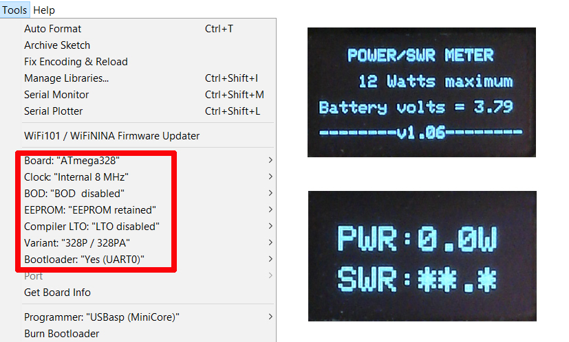
Now start the Arduino IDE and load QRP_POWER_METER.ino. Open the Tools menu and replicate the settings shown below, then hold the Shift key and click the Upload button. When programming is complete the display should show the startup screen, followed a few seconds later by the measurement screen.
While still connected to your computer, measure the internal dc reference voltage on pin 21 with a multimeter. This voltage is stable but not accurate and can vary between 1.0V and 1.2V. Replace the default value in the Calibration Factors section of the code with the measured value and load the program again.
Now connect up the battery, charger and on/off switch, put the switch in the on position and the screen should display an accurate battery voltage. With a suitable 50 ohm load on RFout, apply varying power levels to RFin and observe the readings on the display which should be within 5% of the true values between 1 and 10 Watts. If the error is significantly higher, it can be corrected by making small adjustments to the calibration factors in the code.
Check the VSWR readings using different loads and power levels. Again, the accuracy should be better than 5% between 1 and 10 Watts.
The software uses an exponential filter to smooth out variations in the display. The weighting factor is set to 50 in lines 99 and 100 of the code. This can be adjusted up or down to obtain a stable display.
The maximum power reading is about 12 Watts as the forward voltage approaches the upper limit of the ADC input range.
The absolute maximum input level before component damage occurs is about 25 Watts.
PARTS LIST
| Circuit Reference | Value | Package |
|---|---|---|
| C1, C2 | 10nF 50V X7R | 0805 |
| C3, C5 | 100nF 50V X7R | 0805 |
| C4 | 4µ7 16V Tantalum | 1206 |
| D1, D2 | 1N5711 | SOD323 |
| IC1 | ATmega328P-PU | DIL28 |
| R1, R2, R5, R6 | 100R 1% | 1206 |
| R3, R7 | 18k 1% | 0805 |
| R4, R8, R11 | 10k 1% | 0805 |
| R9 | 39k 1% | 0805 |
| R10 | 10k 5% | 0805 |
| SK1 | SMA_EDGE_CONNECTOR | |
| SK2 | SMA_EDGE_CONNECTOR | |
| SK3 | JST B4B-XH-2 | |
| SK4 | 3+3 way PCB header | 0.1" pitch |
| SK5 | JST B2B-XH-2 | |
| SK6 | JST B4B-XH-2 | |
| SK7 | JST B2B-XH-2 | |
| TP1 | 1 Way PCB header | |
| TP2 | 1 Way PCB header | |
| Tr1 | BN-43-202 Ferrite Core | |
| Miscellaneous: | ||
| Tobacco tin | ||
| Sub-miniature rocker switch | ||
| TP4056 charging module | ||
| 3.7V LiPo battery | ||
| OLED display 0.96" 128x64 3.3V compatible | ||
| Display Bezel | ||
| JST plugs 2 and 4 way |